










Synchronous Electric Motors: Core Concepts and Operational Mechanics
1. Core Definition of Synchronous Electric Motors
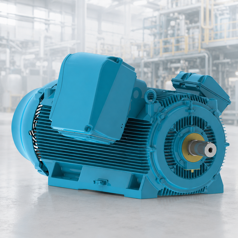
Synchronous electric motors fall under alternating current drive equipment. Their core trait lies in the rotor rotating at an identical angular velocity as the revolving magnetic field generated by the stator assembly. In steady-state operation, the rotor magnetically interlocks with the stator’s rotating flux, delivering fixed rotational speed strictly tied to grid power frequency. This inherent constant-speed feature makes synchronous electric motors the top pick for scenarios demanding ultra-precise rotational speed regulation.
Most people know electric motors convert electrical energy into mechanical motion, yet few recognize the diverse structural and operational schemes designed for this conversion. While a single motor type could theoretically cover general drive demands, electrical engineers develop multiple motor variants for targeted performance advantages. Motors can be powered by direct current, alternating current, or hybrid AC-DC power supplies, each adopting exclusive energy conversion logic. This broad classification yields abundant DC and AC motor categories, with synchronous electric motors standing out among AC types thanks to their unique operational merits for precision workflows.
Synchronous electric motors are engineered to overcome the inherent drawbacks of induction motors, the most mainstream AC motor category. As the name implies, induction motors generate torque via electromagnetic induction, which inevitably creates a speed deviation known as slip. Slip refers to the rotational speed gap between the stator’s alternating flux field and the physical rotor rotation—a direct byproduct of induction-based torque generation. Though slip has negligible impact on ordinary drive tasks, it disqualifies standard induction motors from precision timing equipment, hence labeling them asynchronous machines.
By contrast, synchronous electric motors feature an output rotating frequency perfectly matching the input AC power frequency. Their rotational speed maintains a fixed proportional relationship with supply current, enabling deployment in timing clocks, metal rolling mills, vintage turntables and more. Though they lag induction motors in output power range and model diversity, synchronous electric motors hold irreplaceable value in all projects requiring rigid timing and consistent rotational speed. If you are looking to source synchronous electric motors, feel free to reach out to our team for tailored support.
2. Core Structural Parts of Synchronous Electric Motors
The whole set of synchronous electric motors relies on several core assemblies cooperating to guarantee stable, efficient running. Below breaks down each key component and its functional role:
Stator
As the stationary framework of synchronous electric motors, the stator is fabricated from laminated silicon steel sheets, with embedded slots distributed along its inner wall for winding installation. Its central function is generating the rotating magnetic field that drives overall motor operation.
Stator Windings
Manufactured with heavy-duty enamel-insulated copper wire, stator windings are wired into either three-phase star or delta layouts and embedded inside stator slots. When energized by three-phase alternating current, these windings produce the continuous revolving magnetic field inside the motor cavity.
Rotor
The rotating core unit of synchronous electric motors adopts a cylindrical shape with magnetic poles arranged on its outer circumference. Identical to the stator, the rotor uses stacked silicon steel laminations to boost magnetic permeability and cut down eddy current energy loss.
Rotor Field Windings
Composed of enamel-coated copper wire coiled around rotor poles, these windings receive direct current from an auxiliary exciter unit. The DC input creates a stable magnetic field on the rotor, enabling magnetic locking between rotor poles and the stator’s rotating flux field.
Exciter
Mounted coaxially on the same drive shaft as the rotor, the exciter acts as a low-power DC shunt generator. During motor operation, it independently produces direct excitation current and feeds it into rotor windings, forming a self-sustaining excitation supply loop.
Slip Rings & Carbon Brushes
Two phosphor bronze slip rings are fitted onto the rotor shaft of synchronous electric motors. Paired carbon brushes maintain constant physical contact with slip rings, transmitting DC excitation power from the exciter to rotor windings with minimal energy loss and smooth power transfer.
3. Unique Operational Characteristics of Synchronous Electric Motors
- No inherent self-starting capability: External auxiliary equipment must accelerate the rotor to a rotational speed close to synchronous speed before magnetic synchronization can take effect.
- Constant-speed operation under fixed grid frequency: Once locked into sync with supply frequency, the rotor’s rotational speed remains unchanged regardless of load fluctuations within the motor’s rated torque range.
- Adjustable power factor operation: This exclusive feature allows synchronous electric motors to serve as reactive power compensation equipment for power grids and optimize overall system power factor.
- Since synchronous electric motors can operate under both leading and lagging power factor states, they are widely applied for grid power factor correction. Running at no load, they deliver a leading power factor, making them a viable alternative to static capacitor banks for power system reactive power compensation. They are also prioritized for low-speed, high-torque heavy-load equipment, including industrial rolling mills, wood chippers, mixing agitators, large water pumps and air compressors.
4. Working Mechanism of Synchronous Electric Motors
Sharing a similar outer stator-inner rotor layout with induction motors, synchronous electric motors generate driving torque through magnetic field interaction. Depending on equipment size and application scenarios, they can be configured for single-phase or multi-phase AC input power.
The stator structure mirrors that of induction motors, with copper or aluminum coils wound over laminated iron cores. Alternating current flowing through these coils creates a revolving magnetic field inside the motor. The most prominent structural difference lies in the rotor design: the rotor carries a permanent magnetic field, produced either by built-in permanent magnets or DC-fed rotor windings. This fixed rotor magnetic field comes with fixed north-south poles, which eventually align with the poles of the stator’s rotating flux field, delivering precise rotation proportional to supply AC frequency. Rotor poles fall into two categories: salient poles protruding from the rotor surface and non-salient poles embedded within internal rotor slots.
External startup assistance is mandatory for synchronous electric motors. At standstill, the static rotor cannot instantly lock its poles onto the fast-spinning stator flux field due to rotational inertia. Based on rotor excitation modes, synchronous electric motors are split into two major groups: non-excited synchronous electric motors and current-excited synchronous electric motors.
Synchronous electric motors are classified as doubly-excited electrical machines, meaning they accept two independent power inputs. The stator’s three-phase windings carry alternating current to generate a rotating three-dimensional flux field, while the rotor windings powered by direct current form a stationary constant magnetic field.
At any given moment, rotor and stator poles may carry identical magnetic polarity, generating repulsive force on the rotor; in the next instant, opposite polarities form and create magnetic attraction. However, the rotor’s mechanical inertia prevents continuous rotation under alternating attraction and repulsion, leaving the rotor stationary. This explains why synchronous electric motors cannot self-start.
Operators need external mechanical drive devices to spin the rotor in the same rotational direction as the stator’s magnetic field until its speed nearly matches synchronous speed. Once magnetic locking between rotor and stator flux fields occurs, the external startup apparatus can be disconnected, and the synchronous electric motor maintains steady synchronized rotation autonomously. Contact our team to obtain a free technical quotation for synchronous electric motor solutions.
5. Classification of Synchronous Electric Motors
Synchronous electric motors are categorized primarily by the excitation method used to pull the rotor into synchronous speed, divided into non-excited synchronous electric motors and current-excited synchronous electric motors.
Non-excited Synchronous Electric Motors
This subclass requires no external excitation voltage to initiate operation and relies on ferromagnetic rotor materials to interact with the stator’s revolving magnetic field. Three mainstream sub-types exist as follows:
- Hysteresis Synchronous Electric Motors
The rotor shaft is wrapped with a ferromagnetic hysteresis ring set within non-magnetic base material. The stator’s rotating flux induces dual magnetic poles on the ring, yet hysteresis loss creates a phase lag between rotor flux and stator flux. This angular offset between the two magnetic fields generates continuous driving torque. Hysteresis synchronous electric motors run with low operational noise, making them ideal for audio equipment such as turntables and magnetic tape recorders. - Synchronous Reluctance Motors
These devices produce motion by leveraging magnetic attraction and reluctance effects. Their structural layout resembles stepper motors and induction motors, with a stator fitted with prominent pole coils that generate magnetic flux. The rotor is manufactured from ferromagnetic metal with a modified squirrel-cage profile, featuring recesses, magnetic barriers and internal slots. When rotor and stator poles align, magnetic flux travels through low-reluctance paths; misalignment forces flux to take longer, high-reluctance routes, producing reluctance torque that pulls the rotor back into the aligned low-reluctance position. Many designs enable the rotor to accelerate into synchronous speed automatically, outputting highly accurate rotation. - Permanent Magnet Synchronous Electric Motors
Permanent magnets embedded in the rotor supply a constant magnetic flux, which couples with the stator’s rotating magnetic poles to drive rotation. Variable frequency drives are mandatory for speed and torque regulation, as modifying stator AC supply frequency is the only way to adjust operating parameters.
Current-Excited Synchronous Electric Motors
DC-excited synchronous electric motors represent the sole mainstream variant under this category, requiring both AC stator supply and DC rotor supply. Direct current energizes rotor windings structurally similar to stator coils, generating a fixed rotor magnetic field. This excitation aligns rotor poles with the stator’s revolving flux field to achieve synchronization. Most high-power models above 1 horsepower adopt this rotor scheme, and the term "synchronous electric motor" usually refers to this type in industrial contexts.
6. Comprehensive Summary
Synchronous electric motors deliver irreplaceable performance advantages that induction motors cannot match. Without this equipment category, precision timing devices including analog clocks, audio turntables, automotive windshield wiper assemblies, hard disk drives, signal transmitters, precision recording instruments and microwave control boards would cease to function. Beyond precision rotation, synchronous electric motors improve overall system energy efficiency and mitigate power distribution losses caused by inefficient induction motor operation.
Valuable across all industrial sectors, synchronous electric motors serve dual core purposes: power grid reactive power correction and ultra-accurate constant-speed drive. Though higher in manufacturing cost and structural complexity than induction motors, they remain an indispensable drive option for electrical design engineers.
This guide fully introduces synchronous electric motors, covering core definitions, internal construction, operational theories, product classifications and real-world industrial applications. We hope this technical overview delivers practical reference value for your project planning. For more details about synchronous electric motor products and customized solutions, please get in touch with our professional team anytime.
Related Posts

NORD UNIVERSAL SMI Worm Gearmotor (Low Voltage)
Jua 27, 2026
NORD MAXXDRIVE® Parallel Gear Unit (Standard Model)
Jua 26, 2026
SIEMENS Industrial Low-Voltage Helical Gearmotor
Jua 26, 2026